Generator Control System Solution
Generator Dual Power Supply Control System Solution
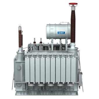
Diesel Generator
Water Supply Control System Solution
Sewage Control System Solution
Fire Pump Control System Solution
High, Medium, and Low Voltage Digital Distribution Solution
Intelligent Motor Control Center Solution
Refining Production Power Distribution and DCS Control System Solution
Oilfield Extraction Power Distribution Solution
Integrated Electrical Control and Instrumentation Solution for Oil and Petrochemical Industries
Call Us
400-117-7797
Email Us
global-sales@chint.com
Home
Products
Sustainability
Call Us
400-117-7797
Email Us
global-sales@chint.com
Main Power Distribution(UL)
Sub Power Distribution(UL)
Final Power Distribution(UL)
Industrial Control(UL)
Generator Control System Solution
Generator Dual Power Supply Control System Solution
Diesel Generator
Water Supply Control System Solution
Sewage Control System Solution
Fire Pump Control System Solution
High, Medium, and Low Voltage Digital Distribution Solution
Intelligent Motor Control Center Solution
Refining Production Power Distribution and DCS Control System Solution
Oilfield Extraction Power Distribution Solution
Integrated Electrical Control and Instrumentation Solution for Oil and Petrochemical Industries
Choose your country & Language
Australia & New Zealand
India
Indonesia
Malaysia
Philippines
Singapore
Vietnam
Saudi Arabia
South Africa
UAE
Kenya
France
Kazakhstan
Netherlands
Italy
Spain
Turkey
United Kingdom
Mexico
USA
Brazil
Colombia
Ecuador
Peru


-metalclad-AC-enclosed-switchgear-banner.png)