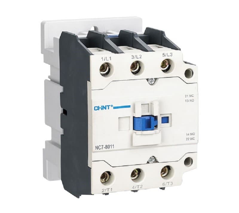
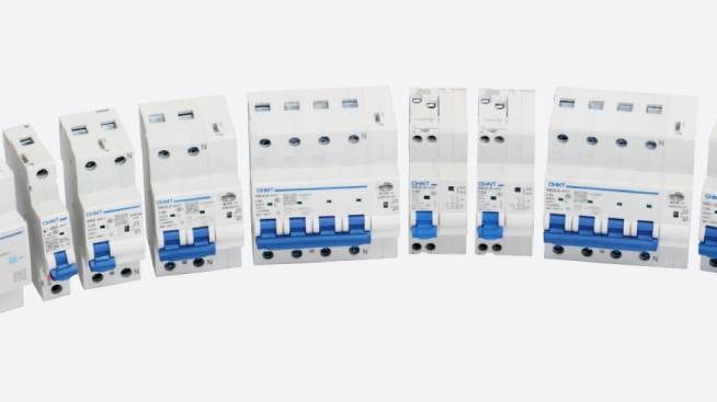
While technology has improved over years, the primary means of controlling electrical circuits remain the same. Among these are contactors , and this article examines the different types of contactors and how they work. It also looks at the differences between contactor and relay , AC contactor and DC contactor.
What Is a Contactor?
A contactor is an electromechanical switch whose function is to make or break the connection between the power supply and the load. The contactor is electrically controlled and usually powered at a much lower level than the switched circuit. For example, you would have a 24-volt coil electromagnet that controls a 230-volt motor switch.
A contactor’s applications include controlling electric motors, thermal evaporators, lighting, capacitor banks , heating, and other electrical loads. Contactors range in size and capacity. You have those that you can easily lift with your hand to massive ones measuring about a meter on the side. You also have those with a breaking current ranging from a few amperes to thousands of amperes and those from 24V DC to many kilo volts.
Types of Contactors
Knife Blade Switch
It is the oldest type of contactors and uses ON and OFF electric motors. The knife blade switch consisted of a strip and a lever. The lever serves to pull the metal strip up and down, making this contactor a manual operation. It has several shortcomings which led to its discontinued use. These challenges include
- High incidences of arcing led to a short life span for the contactor
- Had safety risks
- Was vulnerable to moisture and dirt
- Double Break
Manual Contactor
This contactor was a replacement and improvement on the knife blade switch. It, however, still features manual operation. Other key features are
- Double break contacts, which can open the circuit in two places simultaneously, providing more current in smaller spaces.
- Properly enclosed unit protecting the inner parts
- Safer operation
- Smaller size
Magnetic Contactor
This is the latest contactor design and is the most advanced of them all. It is commonly used in industrial applications due to its features like
- It works automatically
- Offers the safest operation
- Uses the least amount of control current to open and close a circuit.
How Does a Contactor Device Work?
To understand the contactor working, you need to know the various parts of a contactor. There are three essential components of a contactor;
- The coil/electromagnet
- Contacts
- The frame or enclosure
Coil or electromagnet
The coil provides the driving force in a contactor that closes the contacts. It features a coil wound around an electromagnetic core and thus behaves like an electromagnet. The coil has two parts, a fixed one and a movable part with a spring connecting both parts. This structure creates a spring return mechanism.
A rod called an armature is connected to the movable part. When the coil’s force is more than the spring’s force, both contacts connect. When the spring’s force is more than the coil’s force, the contacts disconnect.
The input of the contactor coil could either be AC or DC. This current comes from an external control circuit for the contactor and serves to excite the electromagnetic core. For AC contactors, soft laminated iron is the electromagnetic core material. It helps reduce the eddy current loss. In DC contactors, solid steel is the material for the electromagnetic core as the issue of eddy current does not arise.
Contacts
Contacts perform the current carrying function in a contactor. There are different types of contacts in a contactor, and they are; auxiliary contact, power contact, and contact spring. The power contact has two types that are; stationary and movable contact.
Material for making contacts must have a high welding resistance and stable arc resistance. The material should also withstand erosion and mechanical stress. In high current and DC applications, the material is silver tin oxide, while in low current applications, the material is silver nickel and silver cadmium oxide.
Enclosure
As the name suggests, the enclosure protects the internal parts of the contactor. It shields the contacts from dust, bad weather, explosion hazards, and oil. It also prevents personnel from touching the contacts.
The contactor working, in a nutshell, is as follows
Current from the external control circuit passes through the contactor, exciting the electromagnetic core. In turn, the coil/electromagnet creates a magnetic field which makes the contactor move the armature. A normally closed contact then makes the circuit complete between the fixed and moving contacts. The current is then able to pass through these contacts to the load.
When the current is removed, the coil becomes de-energized, and the magnetic force falls to zero. The spring force is thus higher and pulls back the armature opening the circuit. The design of contactors facilitates rapid ON-OFF action.
Differences Between AC Contactor and DC Contactor
An AC contactor is different from a DC contactor in five main ways;
- An AC contactor electromagnetic core is made of laminated silicon steel sheets, while that of a DC contactor is made from soft steel.
- The electromagnetic core in an AC contactor often has an E shape, while that of a DC contactor often has a U shape.
- An AC contactor comes with a short circuit ring at the end of the static core. It helps eliminate vibration and noise from the electromagnet. A DC contactor does not come with a short circuit ring as it does not need it.
- An AC contactor has a high starting current with a maximum operating frequency of 600 times/hour. That of a DC contactor is about 1200 times/hour.
- A DC contactor uses a magnetic quenching arc, while an AC contactor uses a grid arc as an extinguishing device.
Contactor vs. Relay
Since contactors and relays are often confused with one another, a contactor vs. relay comparison will help you tell the difference and know which one to pick.
Size: contactors are relatively larger in comparison to control relays
Current switching capacity: relays can carry loads of up to 10A or less, while contactors carry loads higher than 10A.
Applications: relays are commonly used in single-phase control circuits, whereas contactors are built for 3-phase applications.
System voltage: relays are typically rated up to 250V only, which is less than contactors, which are often rated up to 1000V.
Open/closed contact standards: contactors are typically designed to operate almost exclusively with Normally Open contacts. On the other hand, relays have both Normally Open/Normally Closed based on the intended function.
Safety features: relays carry low power and, as such, do not often have security features, while contactors come with security features like arc suppression and spring-loaded contacts since they carry higher loads.
Maintenance: contactors are easy to maintain than relays, which can often be impossible even to repair.
Finally, relays have faster switching action compared to connectors.
Conclusion
Contactors are indispensable devices in the control of a circuit and come with added safety features. As with every electrical device, it is vital to ensure you find one that matches your needs and function. You also need a reliable supplier like CHINT which offers genuine products meeting global standards like IEC.
Further, you want to have more options in design and utility as well as professional support. These factors help you identify a suitable gadget that promotes safety and gives you value for your money.


.png)
.png)


