Table of Contents |
Power transformers facilitate consistent transmission of electricity. Their placement within power grids is calculated to maximize the effectiveness of distribution. A power transformer is used to efficiently raise or lower voltages to optimal levels. This is required for both safe energy transmission over long distances and distribution at safer, reduced voltages for household and industrial usage.
Understanding how these critical devices function and the diverse applications they serve is important, particularly for professionals working within the electric power sector.
What is a Power Transformer?
A power transformer is a static electrical device. It transfers electric power between circuits. It doesn’t require any moving parts since it leverages electromagnetic induction. It utilizes the principle of electromagnetic induction to efficiently alter voltage levels for power transmission or distribution purposes. It consists of two or more coils of wire linked by a common magnetic core.
A power transformer contains two coils of wire. They are known as the primary and secondary windings. The windings are wrapped around a central laminated iron core. This iron core is made of stacked steel laminations. It acts to concentrate and guide the magnetic flux lines produced by the current flowing thrwork/jcr:coough the winding coils. The entire magnetic and electrical assembly is housed inside a steel tank that is filled with insulating oil. This oil serves to insulate and cool large power transformers during operation. Additionally, larger utility transformers may contain other internal components such as bushings, cooling ducts, tap changers, and protection circuits to enable adjustments during power transmission.
How Does a Power Transformer Work?
The power transformer working principle is based on electromagnetic induction. The magnetic field in one circuit inducing a voltage in a nearby circuit causes it. Specifically, changing the magnetic field produced in the primary wire coil because of alternating current passing through it induces a voltage in the secondary coil, which is wrapped around the same iron core.
The transformation process inside a power transformer is quite interesting. The steps involved include:
An alternating current is passed through the primary winding. It establishes a changing magnetic field around the transformer’s iron core. This occurs due to the magnetic effect of current flow.
As the alternating voltage cycles, the magnetic field strength inside the core correspondingly expands during one half of the cycle and collapses back during the other half.
This continuously varying magnetic flux permeates from the inner core and cuts through the secondary winding wrapped around the same iron core structure.
According to Faraday’s law of electromagnetic induction, the changing magnetic field produces an electromotive force (EMF) in the secondary winding coils as the flux cuts through it.
The magnitude of induced EMF in the secondary depends upon factors like the rate of change of flux, number of turns in the winding, and other transformer specifications.
By adjusting the number of turns in the two windings, the induced voltage in the secondary can be stepped up or down relative to the primary voltage using the transformer’s turn ratio.
This transformed voltage is then available for onward power transmission or distribution applications after passing through the isolated secondary winding.

Application Scenarios
Power transformers have various important application scenarios depending on the voltage transformation needs. They enable efficient power delivery across vast networks. Some of the most common uses of a power transformer include:
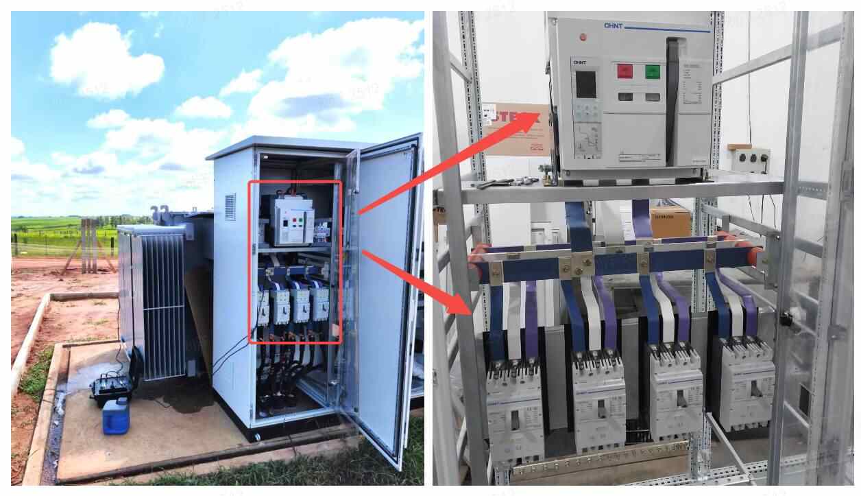
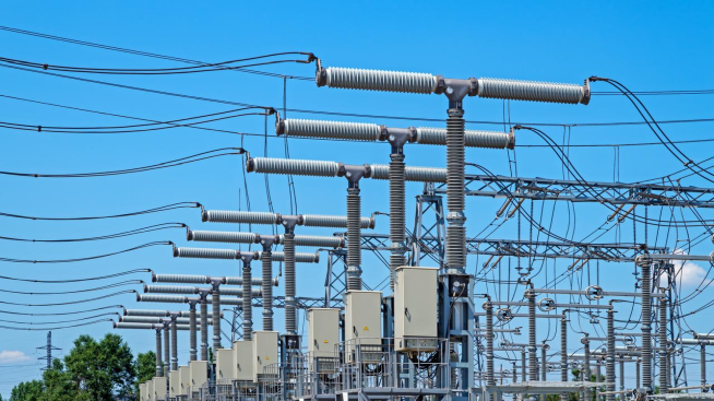
▸ Substations
Transformers in substations play a key role in high-voltage transmission. Here, step-up transformers elevate distribution voltages for efficient long-distance power transmission through transmission lines. On the other hand, step-down transformers lower transmission voltages for distribution to towns and cities through distribution lines.
▸ Copper Mines
Because of the fire and explosion risks underground, copper mines require specially designed isolated transformers. These transformers have enclosures surrounding the coil assemblies to prevent arcing from causing ignitions in hazardous mine atmospheres.
▸ Power Plants
Within thermal and hydroelectric power plants, generators produce electricity at a voltage suitable for efficient generation, which may differ from transmission standards. Hence, station service transformers adjust the voltages to the required transmission levels before sending them out through transmission lines.
▸ Residential Distribution
Pole-mount transformers located on utility poles along streets help reduce distribution voltages even further for safe usage levels in homes. Pad-mount transformers installed above ground at housing complexes perform a similar voltage conversion function for supplying various residential loads.
Common Voltage Range of Power Transformers
Power transformers are used across a wide voltage range depending on their capacity and intended purpose. The common voltage ranges for power transformers can be categorized based on their usage and the specific requirements of the power systems they serve. Common power transformers ranging from 110kV to 750kV are crucial for power transmission, primarily used for:
110kV Power Transformers: For regional power distribution, higher voltages are stepped down for industrial and commercial use.
220kV Power Transformers: Ideal for long-distance transmission, linking power stations with substations to minimize energy loss.
420kV Power Transformers: Used in the backbone of the power grid for inter-regional transmission of significant power loads.
500kV Power Transformers: Designed for ultra-high voltage lines, connecting major cities or provinces to ensure grid stability.
750kV Power Transformers: For high-capacity, long-distance transmission lines, often spanning countries or continents for efficient power delivery.
These transformers are engineered to reduce energy loss during long-distance transmission, ensuring efficient and reliable electricity supply.
Reputable power transformer manufacturers ensure high-quality products are available from distribution level voltages up to ultra-high transmission voltages. CHINT is one such globally reputed provider with years of experience in the energy sector. You can visit our website to check out all of our power transformers.
Conclusion
Power transformers play an indispensable but often unnoticed role in enabling the reliable transmission and distribution of electric power all over the world. Gaining practical insights into their electromagnetic operating principles, diverse deployment scenarios, and technical requirements benefits professionals engaged in this domain.