Table of Contents |
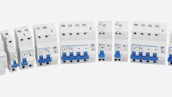
The NCH8 Modular Din-rail Contactor is a high-performance electrical switching device. It’s designed for efficient control and protection in various electrical systems. It’s engineered to provide reliable circuit management in industrial and commercial applications. This article provides a comprehensive, step-by-step installation guide for this robust modular contactor.
Tools Required
Safety should always be a first priority. Before beginning, disconnect the power source completely. This is vital to prevent potential electrical hazards. Proper preparation and tools are essential for a successful and safe modular contactor installation. The tools required include:
- Wire Strippers: Precision tools for removing wire insulation without damaging the underlying copper conductor.
- Crimping Tools: These pliers help create secure connections between wire and terminal lugs.
- Appropriately Sized Wires: Select wires that match the contactor’s current rating and specifications.
- Wire Lugs: Metal connectors that facilitate secure electrical connections.
- Screwdrivers: For handling different mounting and connection requirements.
- Insulating Gloves: These prevent electrical shock during installation.
- Protective Goggles: Essential eye protection against potential sparks.
- Multimeter: Crucial for testing electrical continuity and verifying proper installation.
NCH8 Modular Contactor Installation Process
Installing the NCH8 Modular Contactor requires precision and a systematic approach. Follow these guidelines:
1. Verify the Contactor Model for Compatibility
Thoroughly examine the NCH8 contactor’s technical specifications. Compare them against your electrical system’s requirements. Confirm the current rating, voltage specifications, and environmental compatibility. The aim is to prevent operational failures or safety risks.
2. Select a Suitable Installation Location
Identify a location that meets strict electrical installation criteria. It should be free from excessive moisture, dust, and direct sunlight. The chosen AC contactor area must provide adequate ventilation and maintain consistent temperature. It should offer protection from potential mechanical damage or environmental stress.
3. Align the Contactor with the DIN Rail
Position the top edge of the NCH8 contactor precisely parallel to the upper section of the DIN rail. Ensure perfect horizontal alignment.
4. Secure the Contactor to the DIN Rail
Apply controlled, even pressure along the bottom edge of the contactor. Pressing firmly until you hear a distinct clicking sound. This confirms the secure attachment of the AC contactor.
NCH8 Modular Contactor Disassembly Process
Understanding the proper disassembly technique is crucial for maintenance or replacement scenarios. Follow these guidelines for disassembling the NCH8 modular contactor:
1. Use a Flathead Screwdriver
Carefully insert a flathead screwdriver into the designated actuating port. Apply gentle, controlled pressure to disengage internal locking mechanisms. Use minimal force to prevent potential damage to the internal components of the CHINT contactor.
2. Lift and Detach the Contactor
Gradually lift the bottom section of the contactor. Create a slight separation from the DIN rail. Maintain a steady, controlled motion to prevent abrupt movements.
3. Tilt and Remove the Contactor
Smoothly rotate the contactor forward at a precise angle, typically around 20-30 degrees. Maintain a controlled, fluid motion to ensure complete detachment. The aim is to do it without causing stress or potential damage to the electrical connections or mounting points.

NCH8 Modular Contactor Wiring Process
Follow these detailed steps for a reliable connection:
1. Select Wires with Appropriate Cross-Sectional Area
Carefully reference the CHINT contactor specifications to determine the exact wire cross-sectional area based on its current rating. For NCH8-20, select 1-4 mm² copper wires; for NCH8-40, choose 2.5-16 mm² copper wires to ensure optimal electrical performance and safety.
2. Strip the Outer Insulation of the Copper Wire
Use precision wire strippers to carefully remove 10-12 millimeters of outer insulation from the copper wire.
3. Crimp Wire Lugs onto Wire Ends
Utilize professional-grade crimping pliers to attach wire lugs securely to the exposed copper wire ends. Ensure a tight, reliable connection.
4. Tighten the Wires at the Specified Torque
Use a calibrated electric screwdriver to tighten wire connections at precise torque values. For NCH8-20/25, apply 0.8 N.m. for M3.5 connections; for NCH8-40/63, use 2 N.m. for M5 main contacts. For the coil, use M3.5 and 0.8N.m.
NCH8 Modular Contactor Testing Process
Testing is a crucial final step to verify the installation’s integrity and the functionality of the CHINT contactor. Follow these steps:
1. Conduct a Continuity Test on Main Contacts
After powering up, systematically test the main contacts using the multimeter. Verify electrical continuity, checking for consistent and reliable connection across all primary electrical pathways.
2. Use a Multimeter to Verify Normal Operation
Use the multimeter to perform comprehensive electrical performance tests. Measure voltage, current, and resistance to confirm the contactor’s operational integrity and compliance with manufacturer specifications.
3. Refer to Fault Analysis Guide
Methodically cross-reference any detected anomalies with the manufacturer’s comprehensive fault analysis documentation. Systematically diagnose potential issues regarding the NCH8 AC contactor. Implement recommended troubleshooting protocols to resolve electrical performance challenges.
For a more direct look into the installation process of the NCH8 Modular Contactor, check out our YouTube video:
Conclusion
Installing the NCH8 Modular Contactor requires precision, technical knowledge, and a commitment to safety. Each stage demands careful attention to detail. By following these systematic guidelines, you can achieve reliable electrical system integration. At CHINT, we pride ourselves on delivering advanced electrical solutions. For any additional support or guidance, feel free to get in touch with our technical support team.
.png)