Table of Contents |
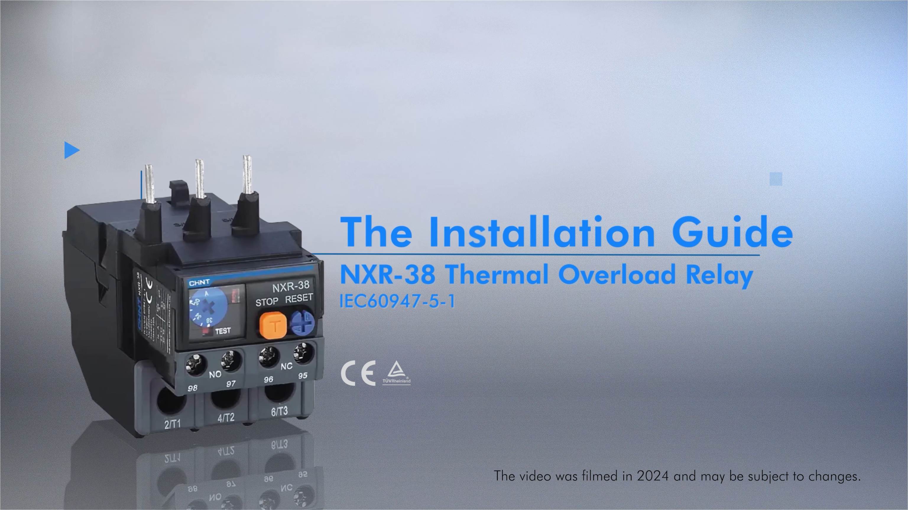
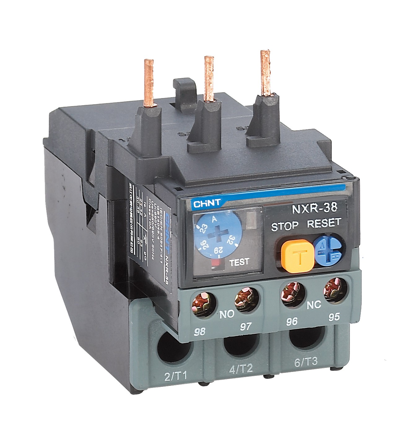
Thermal overload relays are valuable devices. They help protect electrical motors from potential damage. It’s specifically the damage caused by excessive current. The NXR-38 Thermal Overload Relay is a popular device in this category. It monitors motor current and prevents overheating. This guide provides thorough instructions for installing, commissioning, operating, and troubleshooting the NXR-38 relay. The goal is to help you ensure safe and efficient motor operation.
Preparation
Follow the following preparation steps for a smooth and safe setup of this 3 phase overload relay:
1. Safety Precautions
Always prioritize safety during installation. Disconnect the power source. Wear insulating gloves and protective goggles.
2. Tool Checklist
Here’s what you’ll need for a successful thermal overload relay installation:
- Wire strippers
- Crimping tools
- Screwdrivers
- Multimeter
- Appropriate wires
- Wire lugs
- Insulated gloves
- Protective goggles
Installation Steps
Following these steps for proper mounting and connection of the NXR-38 Thermal Overload Relay:
1. Inspection
Before installation, verify that the STOP, RESET, and TEST buttons function normally.
2. Mounting
Carefully attach the AC contactor actuator to the DIN rail. Align the top edge first, then press down firmly to secure the bottom. Then, use a screwdriver to remove the AC contactor terminals 2/T1, 4/T2, and 6/T3.
3. Connecting the Relay
Hang the rear cover hook of the thermal overload relay into the slot of the AC contactor. Precisely align the three conductive rods of the thermal relay 1/L1, 3/L2, and 5/L3 with the terminals of the AC contactor. Press the rods into position. Then tighten the securing screws with a screwdriver.
4. Adjust Current Setting
The current setting is crucial for thermal overload protection. Calibrate the adjustment cam to match the specific working conditions of your motor.
Wiring Instructions
Proper wiring is critical to the relay’s performance and overall system reliability. Follow these recommendations and guidelines:
1. Wire Selection
Choose wires with appropriate cross-sectional areas based on the current rating. This ensures optimal electrical conductivity and safety of the overload relay thermal unit. Refer to this table for the correct selection:
Rated Current (In) |
Wire Cross-Section (S (Cu) mm²) |
12A |
1 ~ 4 |
25A |
1 ~ 6 |
38A |
4 ~ 10 |
100A |
4 ~ 35 |
2. Wire Preparation
Strip insulation to the specified length and crimp wire lugs securely:
- For primary circuit wiring, strip 11 to 13 millimeters.
- For auxiliary circuit wiring, strip 9 to 11 millimeters.
3. Wiring Guidelines
Create clear physical separation between primary and auxiliary circuits. Use cable management techniques to route wires. For NXR-38 auxiliary contact terminals 95 96 (NC or Normal Close Contact) connect in the same loop with contactor terminals A1 A2. Terminals 97 and 98 are Normal Open Contacts (NO).
Use a calibrated torque screwdriver to tighten electrical connections. Follow recommended torque values for each specific terminal type. These include:
Fastening Screw Size |
M3.5 |
M4 |
Tightening Torque (N.m.) |
0.8 |
1.7 |
Testing Steps
Thorough testing is essential to verify the relay’s proper installation and functionality. There are two key checks:
1. Pre-Power Check
Verify the status of the STOP, RESET, and TEST buttons before powering up the system.
2. Post-Power Test
Use a multimeter to perform continuity checks and confirm the normal operation of the thermal overload relay.
Fault Diagnosis and Troubleshooting
Despite careful installation, a thermal overload relay can occasionally encounter operational issues. The following table provides a comprehensive overview of common symptoms, their potential causes, and recommended troubleshooting methods:
Symptom
|
Potential Causes |
Troubleshooting Methods |
Thermal Relay Malfunctions Without Overload
|
Incorrect model selection (too small) |
Replace with a larger specification product |
The current value set lower than the motor’s operating current |
Adjust the cam clockwise to match the actual motor current |
|
Strong mechanical shocks or vibrations |
Inspect the installation site. Ensure the relay is not in a high-impact environment |
|
Frequent motor starts |
Limit motor start frequency to 30 starts per hour |
|
Inadequate wire connections |
Use standard wire sizes. Ensure proper connection torque settings |
|
Thermal Relay does not Operate |
Incorrect model selection (too large) |
Replace with a smaller specification product |
The current value is set higher than the motor current |
Adjust the cam counterclockwise to match the motor current |
|
Oversized wire cross-section |
Use appropriate wire sizes and also apply proper torque settings |
|
Thermal Relay does not Operate |
Relay reset mechanism failure |
Press the RESET button firmly |
Auxiliary contacts not conducting |
Replace the thermal relay |
|
Main or auxiliary circuit damage |
Replace the thermal relay |
Summary
Installing the NXR-38 Thermal Overload Relay requires careful preparation and precise installation. Thorough testing is crucial to ensure proper operation. By following these relay installation guidelines, you can ensure reliable motor protection and optimal performance. At CHINT, we offer reliable electrical solutions. Browse our website to access our detailed documentation.


