Table of Contents |
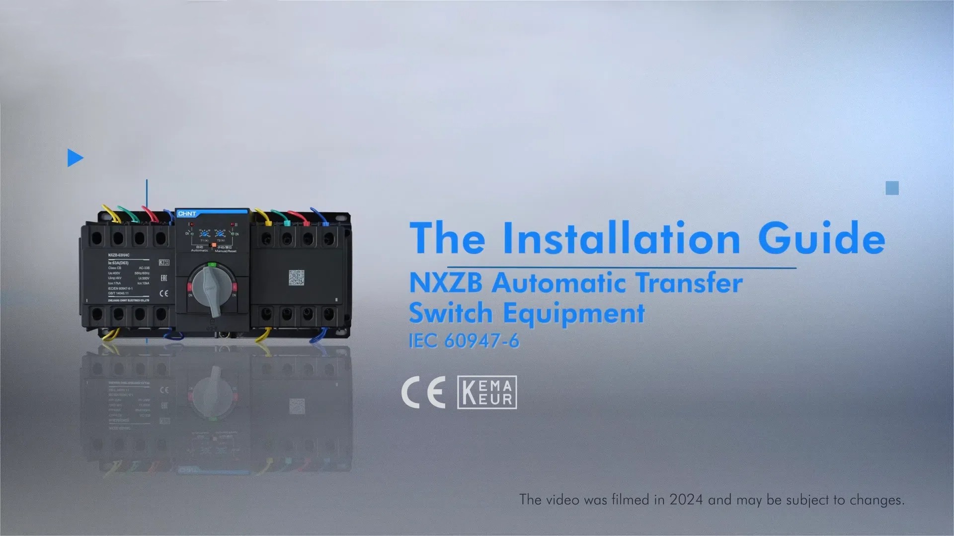
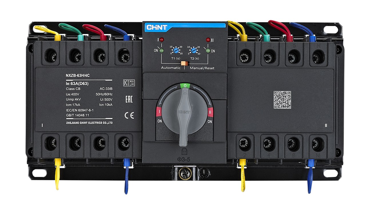
The NXZB Automatic Transfer Switch Equipment (ATSE) is a critical component in electrical systems. It ensures seamless power supply transitions between main and backup power sources. It automatically switches power sources during electrical interruptions. With this, it helps minimize downtime and maintain continuous electrical operations. Proper installation of this equipment is crucial for safe and efficient performance. It ensures reliable power management in various settings.
Safety First: Precautions Before Installation
Disconnecting the power supply is the first and most critical safety step. Make sure to completely shut down electrical connections from all power sources. This prevents potential electrical shocks and reduces the risk of serious injury.
Personal protective equipment is also mandatory during 3-phase automatic transfer switch installation. Wear insulated gloves that protect against electrical currents. Use safety goggles, too, as they shield your eyes from potential sparks or debris.
Before proceeding, thoroughly read the user manual. Understand the manufacturer’s specific guidelines. It ensures correct installation and prevents equipment damage. It also helps you maintain warranty conditions.
Preparing for Installation: Tools and Environment Requirements
Installing an NXZB Automatic Transfer Switch Equipment requires careful preparation and specific tools.
1. Tools Required
Here’s what you will need:
- Electric screwdriver
- Flathead screwdriver
- Scissor
- Wire strippers and cutters
- Insulated gloves
- Safety goggles
2. Installation Environment Checklist
Consider the following when choosing an automatic transfer switch equipment installation environment:
- No Flammable, Explosive, or Corrosive Gases
The installation area must be free from potentially dangerous atmospheric conditions. It’s because these could compromise equipment safety or functionality.
- Dry and Well-Ventilated Area
Choose an install location with minimal moisture and adequate air circulation. The goal is to prevent electrical component degradation.
3. Inspect the Switch and Packaging for Completeness and Damage
Before proceeding, carefully inspect the switch and packaging. Check for any signs of transportation-related wear or structural issues. Verify that all components of the automatic transfer switch equipment are present and undamaged.
Step-by-Step Installation Process
The installation of an NXZB Automatic Transfer Switch Equipment requires precision and attention to detail. Following a systematic approach is key:
1. Mounting the Switch
Proper 3-phase automatic transfer switch mounting ensures its reliability and performance. The mounting location significantly impacts its operational effectiveness.
- Securing the Switch
Use appropriate fasteners matching the specifications of the transfer switch automatic. Ensure tight, uniform attachment to prevent potential movement or vibration during operation. The torque setting for the electric screwdriver should be 2.5 N.m.
- Ensuring Stability
Select a mounting surface that provides maximum stability to the automatic transfer switch. Avoid areas with excessive vibration or mechanical stress that could compromise the switch’s functionality.
2. Connecting the Wiring
Accurate wiring is crucial for the proper functioning of automatic transfer switch equipment. Follow these guidelines:
- Main and Backup Power Supply Connections
Connect the input terminals of the automatic transfer switch carefully. Ensure correct phase and neutral wire placements. Double-check all transfer switch automatic connections before finalizing.
- Load Line Connections
Connect output terminals maintaining strict ABCN sequence. Proper sequencing prevents potential electrical misalignments.
- Secondary Circuit Wiring
Follow the manufacturer’s specifications for secondary circuit connections. Precision is key to maintaining system integrity.
Post-Installation Checks
Comprehensive post-installation verification ensures the switch’s readiness for operation:
- Rotate the handle smoothly and check for consistent mechanical movement without resistance or unusual grinding sounds.
- Carefully inspect all wiring connections, ensuring tight terminals and correct positioning to prevent potential electrical disconnections.
- Set the controller to “Automatic” mode, confirming the switch can independently manage power transitions between primary and backup sources.
Commissioning and Troubleshooting
After installation, powering on the NXZB Automatic Transfer Switch requires systematic verification. Initial steps include checking controller indicator lights, confirming smooth handle rotation, and ensuring all power source connections are stable. Verify that the transfer switch automatic responds correctly when transitioning between main and backup power sources.
For troubleshooting, refer to this table:
Symptom |
Potential Fault Reasons |
Recommended Solution |
Controller Indicator Not Lit |
Power sampling lines disconnected/ broken off |
Check and reconnect wire connections |
The neutral terminal is not connected |
Verify all terminal connections |
|
Blown product fuse |
Replace the fuse |
|
Phase loss or voltage failure |
Check circuit voltage and connections |
|
Four Indicators Flashing Simultaneously |
Controller power supply chip protection |
Wait 10 minutes, then restart |
Controller internal failure |
Replace controller unit |
|
Controller Tripping (Indicator Warning) |
Normal circuit breaker fault |
Examine and eliminate the fault in the normal circuit |
Phase loss in circuit breaker (Phase A Phase N) |
Replace controller or product |
|
Incorrect wiring configuration (especially in Phase A and Phase N) |
Rewire according to User Manual instructions. Check for loose sampling wire |
The fault analysis guide is an essential diagnostic resource. It provides in-depth troubleshooting strategies. While the table offers general solutions, each specific installation may present unique challenges. It is recommended to consult the comprehensive fault analysis guide. It offers detailed step-by-step diagnostic procedures and technical insights. It also has expert-recommended resolution strategies for complex technical issues.
Conclusion
Installing an NXZB Automatic Transfer Switch Equipment requires careful attention to safety, precise technical steps, and methodical execution. At CHINT, we understand the critical nature of seamless power management. That’s why we have designed our equipment to provide reliable performance. Our expert team is committed to supporting professionals and technical enthusiasts. Visit our website for detailed technical documentation, installation videos, and direct contact with our technical support team.


